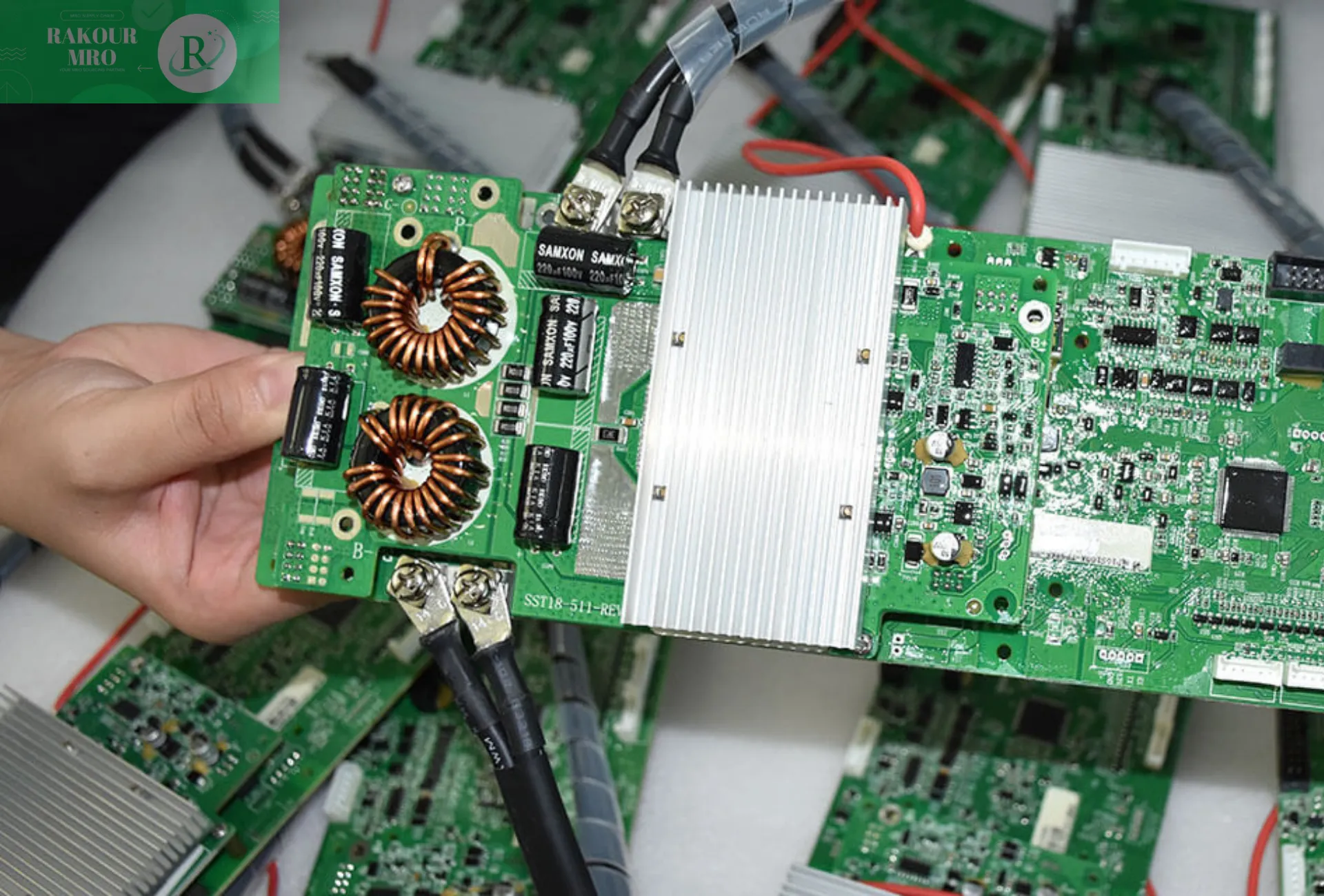
In the new energy sector, the safe and efficient operation of lithium-ion battery packs (BMS) relies on the precise control of a battery management system (BMS). The various cables connecting the BMS, like the “nerves and blood vessels,” are crucial for ensuring BMS functionality. These seemingly ordinary cables directly impact data acquisition accuracy, command transmission efficiency, and system safety. Improper selection or design can lead to data deviations, equipment failures, and even safety incidents. This article focuses on the core types of BMS connection cables in lithium-ion battery packs, detailing their functions, connection methods, and design requirements, providing practical technical references for industry practitioners.
Battery cell monitoring line
Battery cell monitoring line: the "nerve endings" that allow BMS to sense battery status
The battery cell monitoring line is the first line of defense for the BMS to obtain core battery data. It is mainly responsible for collecting battery cell voltage and temperature, providing a basis for the BMS to judge battery health, remaining capacity (SOC) and charge and discharge protection, and is the basis for ensuring battery safety.
Voltage sampling line
Voltage sampling line: accurately control voltage boundaries
Voltage is the most critical parameter in a battery cell’s status. Overcharging can cause cell bulging and lithium deposition, while overdischarging can cause irreversible damage. The core task of the voltage sampling line is to stably transmit the voltage signal of each cell or cell group to the BMS, ensuring that the BMS can quickly respond to voltage anomalies.
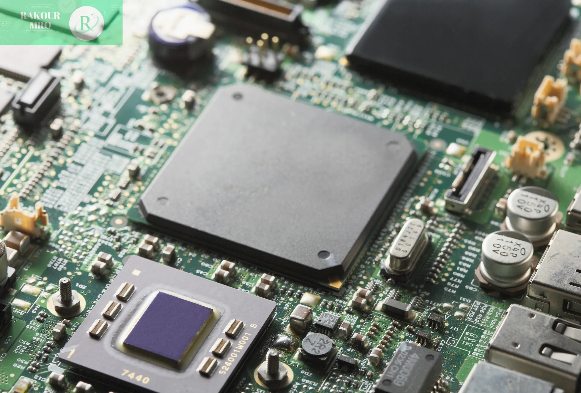
Two common connection methods are available: First, voltage-divider resistor sampling uses a high-precision resistor network to reduce the high voltage of the battery cell (e.g., hundreds of volts in a multi-cell string) to a measurable 0-5V range for the BMS. This approach is low-cost and simple in structure, but the impact of resistor temperature drift on accuracy must be considered. Second, dedicated sampling chips, such as TI’s BQ76PL455A, integrate multiple sampling channels, eliminating the need for additional voltage-divider circuitry. This offers higher accuracy and faster response, making it suitable for high-cell count power battery applications.
Cable requirements must meet two core points: first, the voltage rating must be higher than the maximum voltage of the battery cell. For example, a 60V pack requires a 100V cable to prevent insulation breakdown. Second, low impedance (≤10mΩ), usually using high-purity copper conductors, reduces signal transmission loss and avoids sampling deviation.

Temperature sampling line
Temperature sampling line: strictly prevent the risk of thermal runaway
Abnormal temperatures are the primary cause of thermal runaway in lithium batteries. Temperature sampling cables, equipped with sensors, monitor the temperature of the battery cells or modules in real time, allowing the BMS to promptly initiate cooling or disconnect the circuit.
There are three types of sensors: NTC thermistors are the most commonly used. Their resistance changes with temperature (e.g., 10kΩ at 25°C), and they offer low cost and fast response. PT100/PT1000 platinum resistance resistors offer high precision and good linearity, making them suitable for industrial energy storage applications with stringent temperature requirements. Digital sensors, such as the DS18B20, directly output digital signals, simplifying the circuit but offering slightly lower high-temperature stability.
The connection method must match the sensor type: NTCs connect to the BMS using a 2-wire or 3-wire system, as the 3-wire system can offset cable resistance errors. PT100s must use a 3-wire or 4-wire system to avoid accuracy issues caused by lead wires. Digital sensors often use a single bus, allowing multiple devices to share a single line and providing flexible wiring.
The cable needs to be temperature-resistant (-40°C ~ 125°C) and is commonly made of silicone rubber or fluoroplastic insulation materials. At the same time, a shielding layer is required when it is close to high-voltage lines to reduce electromagnetic interference.

Communication control line
Communication control line: the "information bridge" for interaction between BMS and its internal and external users
The BMS needs to interact with external devices (such as vehicle ECUs and charging piles) and internal modules (such as sampling boards and balancing boards). The communication control line is responsible for data transmission, and its stability directly determines the system's collaborative efficiency.
CAN bus communication line
CAN bus communication line: highly reliable and high-speed channel
The CAN bus is the preferred method for communication between the BMS and external high-speed devices. For example, in electric vehicles, the BMS transmits battery status to the ECU and negotiates charging parameters with the charging station via the CAN bus. It uses differential signaling, consisting of CAN_H (yellow/white) and CAN_L (green/black). The voltage difference is stable at around 2V, providing strong anti-interference capabilities.
Two points should be noted when connecting: First, 120Ω termination resistors should be connected at both ends of the bus to offset signal reflections; second, the distance between CAN_H and CAN_L should be ≤50mm to prevent crosstalk. Cables should be twisted-pair (lay length ≤20mm) with a shield and a characteristic impedance matching of 120Ω to ensure stable communication in complex electromagnetic environments (such as the engine compartment).

RS485/RS232 communication cable
RS485/RS232 communication line: flexible choice for low-speed scenarios
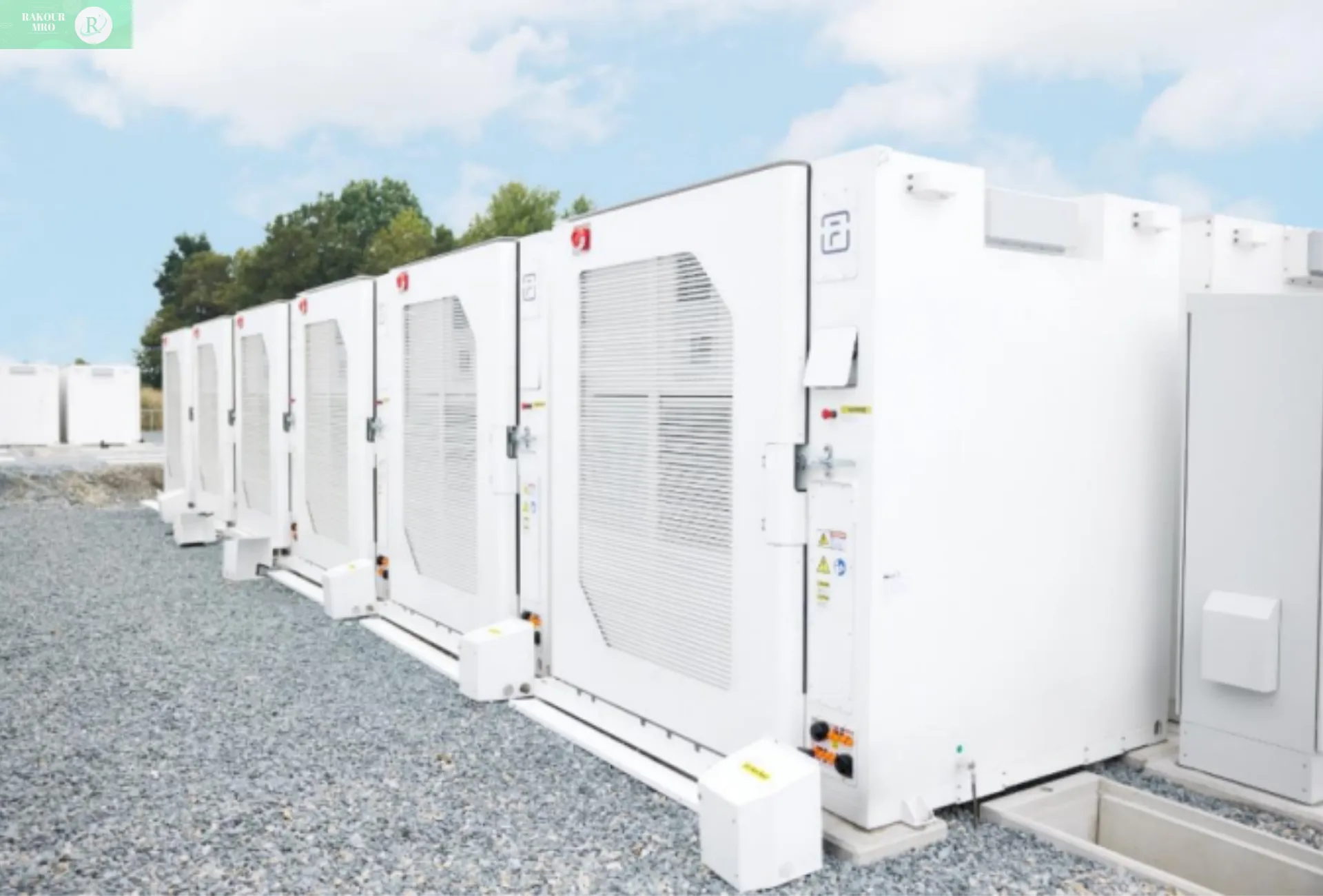
RS485 is suitable for long-distance, low-speed communication, such as connecting a BMS (Battery Management System) and a remote monitoring terminal in an energy storage system. It supports transmission distances up to 1200 meters and supports up to 32 devices. It requires a shielded twisted pair cable, with the A/B wires typically colored brown/orange. RS232 is used for short-distance debugging (≤15 meters). For example, when connecting to a BMS to read logs, only the TX, RX, and GND wires are required. There is no standard color scheme, but be sure to cross-wire the TX and RX wires.
SMBus/I2C communication line
SMBus/I2C communication line: the "collaborative link" between internal modules
Internal BMS modules (such as the main control board and sampling board) are located close together (≤1 meter), making SMBus/I2C communication cables ideal. Both utilize a two-wire system (SCL clock line, SDA data line). SMBus is based on the I2C protocol and adds timeout protection, making it more suitable for power management. I2C offers high flexibility and supports multiple devices.
Cable requirements are simple: short-distance transmission does not require thick wires (such as AWG26-AWG30). SCL and SDA require pull-up resistors of 4.7kΩ to 10kΩ to ensure bus stability. Wiring should be kept away from high-voltage cables to avoid interference.
Power management cable
Power management line: the "energy supply and control center" of BMS
The BMS's own power supply and control of external actuators (such as contactors) rely on the power management line, which is the "energy core" to ensure the stable operation of the BMS.
Main power input cable
Main power input line: the "energy source" of BMS
The main power input cable provides power to the BMS. This power source typically comes from the total voltage of the power pack (converted to 12V/24V via DC-DC converter) or an external auxiliary power supply. It consists of two wires: VCC (red) and GND (black).
When connecting, a fuse must be connected in series with the positive terminal. The rated current should be 1.2-1.5 times the maximum current of the BMS to prevent short-circuit damage. The negative terminal must be reliably grounded (resistance ≤ 1Ω) to prevent voltage drift. The cable current-carrying capacity should be selected based on the BMS power consumption. For example, 2A@12V requires AWG18 cable, and the insulation grade should be ≥ the maximum voltage of the power pack (e.g., a 60V power pack should use 100V cable).
Precharge control line
Precharge control line: "buffer valve" to protect contactors
Directly closing the main contactor will generate a significant inrush current and wear the contacts. The precharge control cable gradually charges the load capacitor by controlling the precharge relay. It consists of two wires: the blue precharge relay control line (BMS output signal) and the green precharge status feedback line (which transmits relay status to the BMS).
The BMS control logic is to first activate the precharge relay, monitor the capacitor voltage via the feedback line, and close the main contactor and deactivate the precharge relay when the voltage reaches above 90% of the pack voltage. The cable should be low impedance (using high-purity copper) and have a voltage rating greater than or equal to the relay coil voltage (e.g., a 24V relay uses a 30V cable).
Contactor control line
Contactor control line: the "executing arm" of BMS
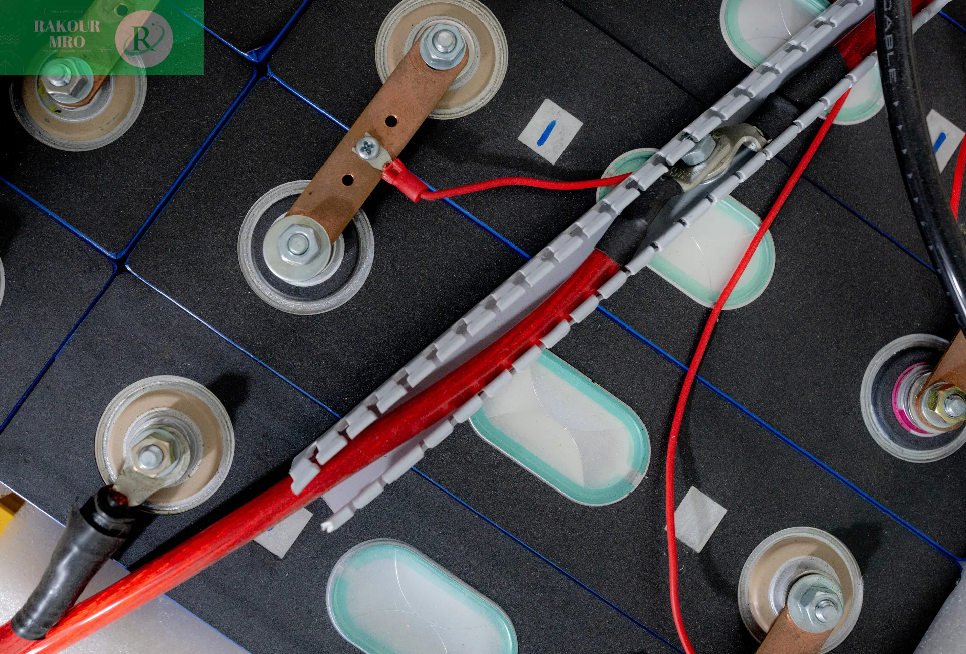
The contactor acts as the “switch” for the high-voltage circuit. Its control lines include the main positive (red) and main negative (black) control lines, as well as a yellow status feedback line. The BMS uses these control lines to open and close the contactor, while the feedback line transmits the actual status, forming a closed-loop control system.
For example, when powering on, the BMS first closes the main negative contactor, then the main positive contactor after precharging is complete. When powering off, the main positive contactor is disconnected first, followed by the main negative contactor. The cable current carrying capacity should be selected based on the relay coil current (e.g., 1A@24V requires AWG20). The insulation grade should be ≥ the coil voltage, and the wiring terminals should be secure to prevent vibration and loosening.
High Voltage Interlock Line (HVIL)
High Voltage Interlock Line (HVIL): The "First Line of Defense" for Safety Protection
High-voltage circuits carry enormous energy, and the HVIL line monitors circuit integrity to prevent accidental live-voltage operation. It establishes a 12V/24V low-voltage loop, connecting all high-voltage connectors (such as charging ports and contactors) in series with the cover interlock switch. The BMS detects the loop’s on/off status.
When all components are properly connected, the loop is closed, and the BMS allows high-voltage power to be applied. If a connector is loose or the cover is not closed, the loop is broken, and the BMS immediately shuts off the high voltage and issues an alarm. Cables must be highly reliable (using high-purity copper), shielded for interference resistance, and routed away from high-voltage cables. Terminals must be waterproof and vibration-resistant.

Charging control line
Charging control line: the "interactive bridge" between BMS and charging piles
When charging, the BMS needs to cooperate with the charging pile, and the charging control line transmits connection confirmation and current control signals.
CC cable: confirm physical connection
The CC line (charging connection confirmation) uses a resistor divider to detect whether the charging gun is properly plugged in. A specific CC resistor is connected in series between the charging gun and the connector. The charging station outputs 12V to the CC line and determines the connection status based on the detected voltage. The BMS will only allow charging to start if the connection is secure. The cable’s withstand voltage must be ≥ the charging connector voltage (e.g., a 1000V cable for 750V DC charging). The terminals must be waterproof.
CP line: regulates charging current
During AC charging, the CP line uses a PWM signal to control current at a frequency of 1kHz. The duty cycle is linearly proportional to the current (e.g., a 50% duty cycle corresponds to 16A). The BMS adjusts the duty cycle, and the charging station outputs current according to the signal. During DC charging, the CP line transmits a fault signal. The cable must be shielded to prevent interference, have a temperature resistance of ≥105°C, and be insulated with XLPE or silicone rubber.
Summary and Outlook
While BMS connection cables represent a low-cost component, they are crucial for the safe and efficient operation of lithium-ion battery packs. In the future, as packs evolve toward higher energy density and higher power, cables will be upgraded to be lightweight (thin-diameter conductors), heat-resistant (ceramic silicone rubber), intelligent (integrated sensors), and environmentally friendly (recyclable materials).