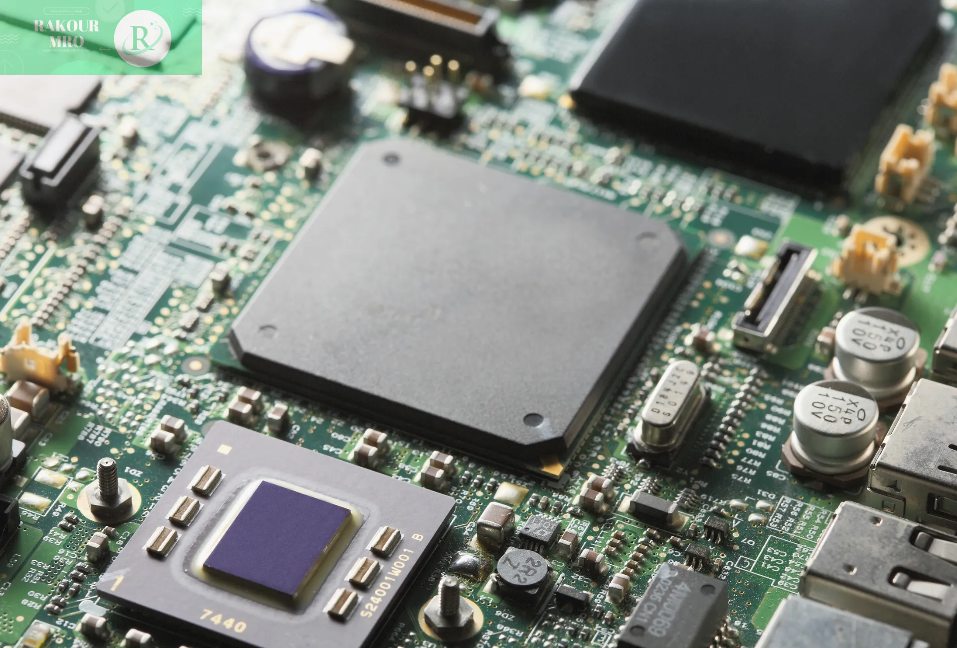
The overall structure of electric vehicles
New energy pure electric vehicles have both intersections and traditional oil vehicles, and their core is a three-electric system. As can be seen from the above figure, electric cars adopt the chassis and body technology of traditional cars, while the engine of oil cars is replaced by “battery”, “motor” and “electrical control”.
The core of electric vehicles – the development of power battery systems generally follows the basic steps and processes of automotive-grade product development:
1) Basic objectives of power battery system design
- From the vehicle performance requirements, consider the operating voltage, available energy, charging and discharging power of the power battery system;
- It is necessary to meet the safety needs of the whole vehicle, including electrical/mechanical/chemical/functional safety
- Consider quality and cost requirements
- Consider manufacturability, testing, packaging
2) Analysis of background information related to PACK development
Electric vehicle type
Different types of cars such as EV, PHEV, REEV have different needs for power batteries. For example, pure electric vehicles require larger battery capacity and higher charging rate.
Target sales area
Purpose: Identify the special requirements of the target area such as laws and regulations, transportation regulations and climate environment.
Target user group
Different target user groups have different needs for power batteries. For example, private car owners often care more about battery life and charging convenience, while online car-hailing drivers care more about charging speed and battery warranty years.
Development of major time node plans
- Content: vehicle winter and summer tests, vehicle announcements, etc.
- Objective: To evaluate the matching between product sample development progress and vehicle development plan.
Product mass production time and demand forecast
- Content: Forecast annual or monthly demand quantity (or vehicle sales planning).
- Objective: To evaluate the production line development progress and capacity matching capabilities.
Third-party certification requirements
The certification requirements for different countries or local standards are different. Obtaining the corresponding certification can obtain market access rights, which is also conducive to improving the market competitiveness of the products.
Overall architecture of power battery system
1) Internal and external interface relationship of power battery system
External interface between PACK and vehicle
- Mechanical installation space and fixation with the vehicle chassis;
- Electrical connection interface with the vehicle's high-voltage distribution box;
- Electrical connection interface with vehicle controller unit, low voltage power supply (12VDC or 24VDC)
- Ground connection interface with vehicle ground;
- Exhaust interface for maintaining pressure balance and emergency emissions with the external environment.
Interfaces between internal subsystems
- Mechanical connection: mechanical installation and fixation of battery modules, battery management system components, high-voltage box, thermal management system components, high- and low-voltage wiring harnesses and connectors, balance valves and other components in the battery box;
- Electrical connection: electrical connection between battery module, BMS, thermal management system components, high and low voltage wiring harness and connectors; electrical connection between battery module and BMS slave (voltage, temperature acquisition), electrical connection between the master control module and slave control module and high voltage box in BMS, etc.
2) Overall architecture of power battery system
According to the structural composition, the main sub-components of the entire power battery system are as follows:
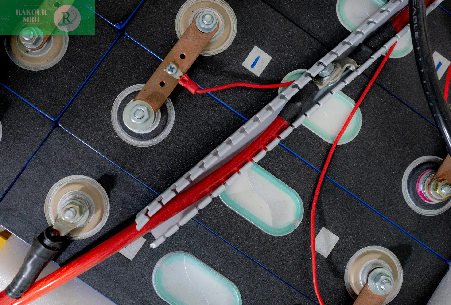
1) Battery module: single battery, module structural parts (end plate, side plate, bottom plate, cover plate, insulation, thermal conduction components, etc.), insulation, battery parameter detection sensors (such as temperature/voltage sampling sensors and wiring harnesses, etc.), electrical connection components (such as battery cells series and parallel busbars, module output poles, etc.).
2) Battery box structural components: battery box (upper cover, lower housing), fixed/support structural components (bracket, press plate/strip, etc.), sealing components (such as sealing strips), balance valve (with explosion-proof functions), standard parts (such as bolts, nuts, gaskets, etc.) and other components.
3) Electronic and electrical components: battery management system, relays, fuses, current sensors, precharge resistors, high/low voltage wiring harnesses, connectors and other components.
4) Thermal management system components: cold plate, hose, pipe joint, elastic support, resistive wire/heating film, etc.
5) Functional components: balancing explosion-proof valve, snap buckle, cable ties, sealing rings/gasses, sealing glue, thermal conduction glue, etc.
3) System architecture of single/multiple power batteries
Usually, a passenger car only has one power battery pack. The architecture diagram is as follows, and the dotted frame defines the boundaries and scope of battery system development.
The boundaries of product development and their relationship with the vehicle and external environment are clearly defined; the boundaries of product internal subsystem development and the connection relationship between subsystems are also clearly defined.
Commercial vehicles (such as electric buses) are usually composed of multiple battery packs and independent high-voltage boxes due to their large layout space, and their system architecture is slightly complex. The BMS main control module and high-voltage electrical components are generally arranged in the high-voltage box, while the slave control module is generally arranged in the battery box.
Relate Articles