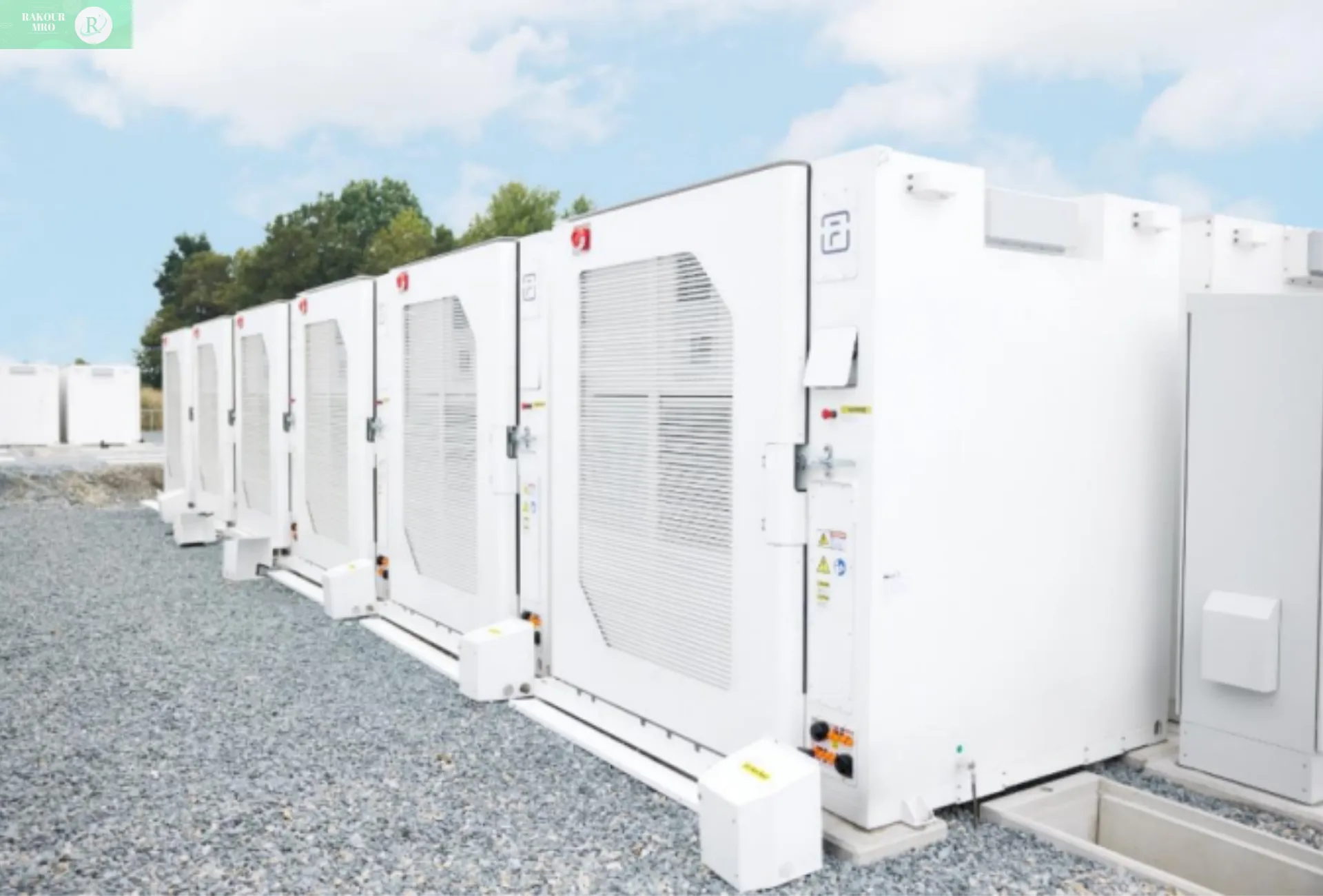
Heat distribution design
Heat distribution design: Make the PACK a "heat steward with precise temperature control"
The essence of the heat distribution problem of the pack is “how to make the battery cells generate heat evenly and dissipate heat efficiently” – if the temperature of some battery cells is too high (hot spots) and some is too low (cold spots), it will lead to “the strong getting stronger and the weak getting weaker”: the hot spots will decay quickly, and the cold spots will not be fully charged and discharged, ultimately significantly shortening the life of the entire pack (for every 5°C increase in temperature difference, the pack cycle life decreases by 10%-15%).
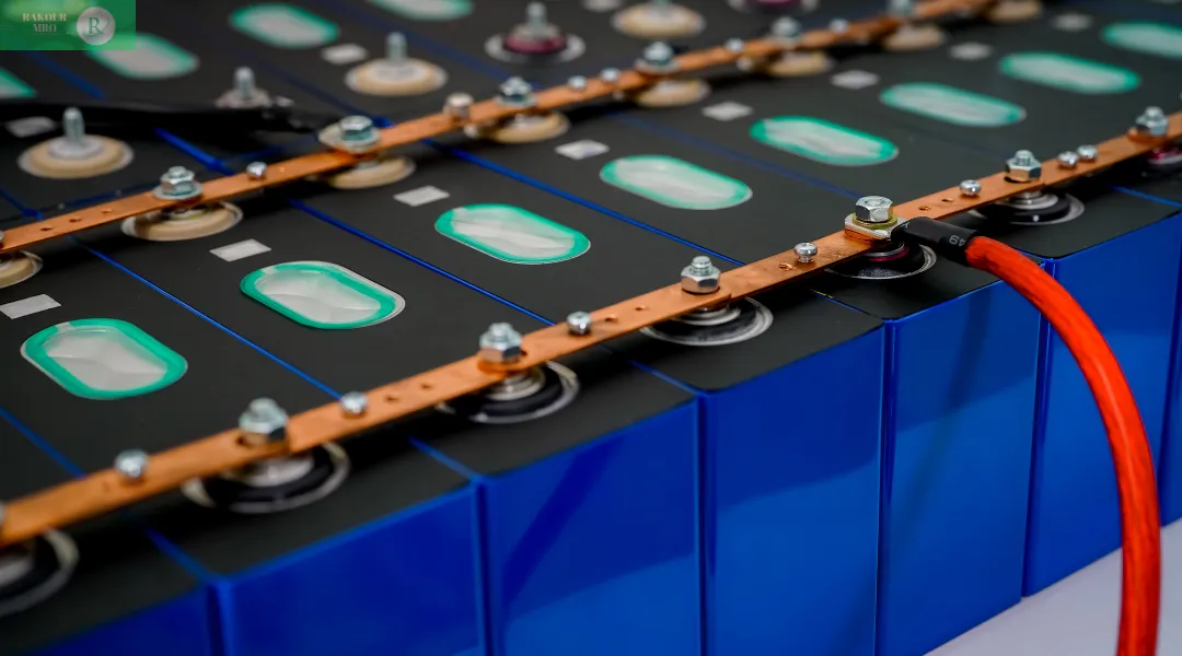
PACK's "heat source" and "heat transfer path"
To control temperature, you first need to understand where heat comes from and where it goes:
Heat sources (heat generation): The core is Joule heating (I²Rt) and polarization heat generated during battery cell charging and dissipation, followed by heat conduction between cells (hot cells transfer heat to the surrounding area). Taking an electric vehicle pack as an example, a single cell generates approximately 5W of heat during fast charging, and 100 cells generate a total of 500W, equivalent to the power of a small electric heater.
Heat transfer paths (heat dissipation): Heat originates from the cell surface and dissipates in three ways:
Heat conduction: Heat is transferred via thermal pads to the pack’s cooling plate/heat sink;
Heat convection: Coolant circulates within the cooling plate, or fans blow air to dissipate heat;
Heat radiation: High-temperature cells dissipate heat to cooler areas via infrared radiation (accounting for less than 5% and primarily serving a supporting role).
The core of thermal distribution design is optimizing the “heat transfer path” to ensure rapid and even heat transfer from the heat generation point to the heat dissipation point, avoiding localized accumulation.
Core challenge: How to solve the problem of “uneven temperature difference”?
The temperature difference within the PACK is mainly caused by two reasons: the difference in the position of the battery cells (the edge battery cells dissipate heat faster than the center battery cells) and the difference in battery cell performance (aging battery cells generate more heat than new battery cells). Engineers solve this problem through two solutions: “active temperature control” and “passive heat distribution”.
(1) Active temperature control: using “dynamic heat dissipation” to eliminate hot spots
Active temperature control is to drive the heat dissipation medium (coolant, air) by external force to remove the heat from the hot spots in a targeted manner. It is suitable for scenarios with large heat generation (such as electric vehicles and fast charging energy storage):
The liquid cooling design (mainstream solution) structure of the electric vehicle PACK: a “snake-shaped water cooling plate” (aluminum alloy material, internal flow channel diameter 5-8mm) is laid under/on the side of the battery cell, and antifreeze (ethylene glycol water solution, freezing point -40℃) is passed into the plate and circulated by a water pump (flow rate 5-10L/min). Temperature Control Logic:
Temperature sensors monitor the surface temperature of the battery cells in real time (one sensor for every 10 cells).
If the temperature in a certain area reaches 45°C (a hot spot), the controller increases the coolant flow to the water cooling plate in that area (locally increasing the flow rate from 5L/min to 8L/min) to accelerate heat dissipation.
If the temperature drops below 15°C (a cold spot), the PTC heater (1-2kW) within the water cooling plate activates to heat the coolant and preheat the battery cells. The result: The maximum temperature difference of the electric vehicle pack during fast charging can be controlled within ±2°C, far superior to the ±8°C achieved with air cooling.
The air-cooled design (a low-cost solution) for the energy storage pack: The battery cells are arranged in a “honeycomb” pattern, with centrifugal fans (at a speed of 2-3m/s) installed at the top and bottom of the pack, creating a “bottom-in, top-out” air duct. Air flows through the gaps between the cells, removing heat. Optimization tip: Install “deflectors” within the air duct to direct air flow preferentially through the center (where the battery cells dissipate heat poorly), reducing the temperature difference between the edge and center (from 8°C to 4°C).
2) Passive Heat Distribution: Using Material Heat Transfer to Balance Temperature
Passive heat distribution uses highly conductive materials (such as vapor chambers and thermal pads) to distribute heat from hot spots to cooler areas. This method requires no additional energy and is suitable for scenarios with low heat generation (such as home energy storage and small electric vehicles).
The heat diffusion magic of a vapor chamber involves placing an ultra-thin vapor chamber (2-3mm thick, made of copper) above the battery cell array in the pack. Filled with a working fluid (such as water), the vapor chamber evaporates upon heating, rapidly transferring heat to the cooler areas.
The working fluid in the cooler areas condenses and flows back to the hot spots through a capillary structure, creating a circulation loop.
The vapor chamber boasts a thermal diffusion coefficient of 1000 W/(m·K), five times that of aluminum alloy. It can distribute heat from a local hot spot to the entire surface within 10 seconds, reducing temperature differences to ±3°C.
The thermal pad’s “gap-filling” function: There’s a tiny gap (0.1-0.5mm) between the battery cell and the cold plate/vapor chamber. Air has a thermal conductivity of only 0.026W/(m・K), hindering heat transfer. Filling with a “silicone thermal pad” (3-5W/(m・K)) fills the gap, increasing heat transfer efficiency by 100 times and ensuring rapid heat transfer from the battery cell to the heat sink.
Extreme scenario: How to deal with “thermal runaway spread”?
Even if a single battery cell fails and triggers thermal runaway (temperatures exceeding 800°C), the heat distribution design must prevent heat spread and the entire pack from catching fire. The core solution is “thermal insulation + pressure relief”:
Thermal insulation layer design: An aerogel insulation sheet (1-2mm thick, with a thermal conductivity of 0.015W/(m·K), which is even more insulating than air) is applied between the battery cells. This localizes the heat from the runaway cell, increasing the temperature of adjacent cells by only 50°C, well below the thermal runaway threshold (200°C).
Pressure relief channel design: A pressure relief valve (50-100mm diameter, burst pressure 0.3-0.5MPa) is located at the top of the pack. High-temperature gases (CO and CO₂) generated by thermal runaway are discharged through the valve in a targeted manner, preventing the pack casing from rupturing and reducing the range of flames.
Mechanical load-bearing design
Mechanical load-bearing design: Make the PACK a "mechanical armor that is resistant to impact and drop"
Throughout its lifecycle, a pack must withstand a variety of external forces: the bumps and vibrations of an electric vehicle, the pressure of stacked batteries, and unexpected collisions and crushing. The core of mechanical load-bearing design is to “use the structure to resist external forces and protect the internal battery cells from damage”—like a layer of armor for the battery, requiring both rigidity (resistance to impact) and flexibility (vibration cushioning).
What “forces” does PACK have to withstand?
Packs in different application scenarios have very different stress types, so the design needs to be tailored to the specific situation:
Core design: three-layer "mechanical protection system"
Engineers use three layers of protection: "frame load-bearing + buffer energy absorption + battery cell protection" to allow the pack to withstand most external forces:
| Application Scenario | Primary Force Type | Force Parameters (Typical Values) | Risk Consequences |
|---|---|---|---|
| Electric Vehicles | Vibration (driving bumps) | Frequency 5 – 2000Hz, Acceleration 5 – 20g | Battery cell loosening, wire breakage |
| Electric Vehicles | Collision (traffic accident) | Impact force 100 – 500kN, Duration 10 – 50ms | Casing rupture, short circuit ignition |
| Energy Storage Station | Stacking pressure (multi-layer stacking) | Bottom PACK pressure 50 – 100kN | Casing deformation, cell crush damage |
| Portable Devices | Drop impact (accidental fall) | Drop height 1 – 2m, Impact acceleration 50 – 100g | PACK cracking, electrolyte leakage |
First Layer: Frame Load-Bearing – Using a “rigid structure” to withstand major external forces
The frame is the “skeleton” of the pack, responsible for withstanding stacking pressure and collision impact. Material selection must balance strength and weight:
The aluminum alloy frame of the electric vehicle pack is made of a 6-series aluminum alloy (such as 6061) in a rectangular frame with a wall thickness of 3-5mm.
Strength Advantage: With a tensile strength of 310MPa, it can withstand a collision force of 500kN (equivalent to the impact of a 50-ton object), with frame deformation less than 5mm, preventing compression of the internal battery cells.
Lightweight Advantage: With a density of 2.7g/cm³, it is 70% lighter than a steel frame (7.8g/cm³), minimizing the burden on the electric vehicle’s range.
Optimized Design: Frame corners are rounded (radius 10-15mm) to avoid stress concentration (right-angled corners are prone to fracture under impact).
The energy storage pack’s steel frame is stacked 3-5 layers high. The bottom frame withstands high pressure (100kN) and is constructed using Q235 steel in a “grid-like” pattern with a wall thickness of 5-8mm.
The compressive strength is 235MPa, and after stacking 5 layers, the maximum frame deformation is less than 3mm, ensuring that the battery cells are not squeezed.
The low cost (steel costs approximately 5 yuan/kg, aluminum alloy approximately 20 yuan/kg) makes it suitable for large-scale energy storage power stations.
Second Layer: Energy Absorption and Cushioning – Using Elastic Materials to Dissipate Impact
After the frame absorbs the primary external force, the cushioning material absorbs the remaining impact energy, protecting the battery cells from direct impact.
Vibration Cushioning: EVA foam/rubber padding (5-10mm thick, 50-70 Shore A hardness) is used between the battery cells and the frame.
Excellent elasticity: Absorbs 5-20g acceleration (due to bumpy driving), reducing the vibration transmission rate to the battery cells from 80% to 20%.
Aging Resistance: Resists brittleness in temperatures between -40°C and 80°C, with a service life of over 10 years, making it suitable for long-term vibration scenarios.
Crash Absorber: Crash Box / Honeycomb Aluminum Electric vehicle packs are equipped with aluminum alloy crash boxes (100-150mm long, 2-3mm thick) at the front and rear ends.
During a collision, the crash boxes undergo controlled deformation (folding and compressing), absorbing over 80% of the impact energy (under a 500kN impact force, the crash box deforms 100mm, reducing the impact force on the battery cell to less than 50kN).
Alternative: Honeycomb aluminum (pore diameter 5-10mm) offers 30% higher energy absorption efficiency than crash boxes, but is more expensive and is primarily used in high-end electric vehicles.
Third Layer: Cell Protection – Using a “partitioning structure” to prevent damage between cells
Even if the frame and buffer layer are damaged, the partitioning structure ensures that the cells do not collide with each other or short-circuit:
Cell dividers: Made of flame-retardant PP plastic (2-3mm thick, UL94 V-0 flame retardancy rating), these “grid-shaped dividers” are individually placed within the grid.
Prevents cells from being crushed during collisions (the dividers have a compressive strength of 5MPa, capable of withstanding the expansion pressure of a single cell).
With excellent flame retardancy, even if a single cell catches fire, the dividers can slow the spread of flame to adjacent cells.
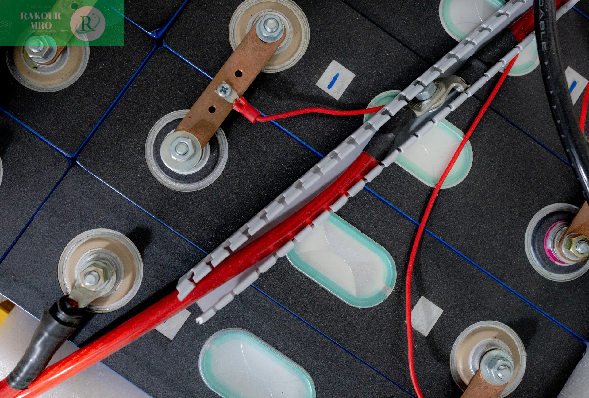
Wire Securing: Corrugated Tubing + Cable Ties: The high-voltage wires (connecting the cells) in the pack are wrapped in flame-retardant corrugated tubing and then secured to the frame with cable ties.
Prevents vibration-induced wear on the wires (corrugated tubing has a wear resistance five times that of ordinary wires).
Prevents wires from coming loose and contacting the cells, potentially causing a short circuit (cable tie tension >50N, ensuring a secure hold).
Verification method: Use "limit testing" to ensure design reliability
The effectiveness of the mechanical load-bearing design is verified through “laboratory extreme testing” to simulate the most severe stress scenarios:
Vibration test: The pack is mounted on a vibration table and subjected to vibration at a frequency of 5-2000Hz for 48 hours according to GB/T 31467.3. After the test, the battery cell voltage and capacity are normal, and the wires are not loose.
Impact test: A hammer is used to impact the side of the pack with a force of 500kN. After the test, there is no cracking of the outer shell, no short circuiting of the battery cells, and the pressure relief valve is functioning properly.
Stacking test: A pressure of 100kN (equivalent to the weight of five layers of energy storage packs) is applied to the top of the pack for 24 hours. The frame deformation is less than 3mm, and the cell thickness change is less than 1%.
“Co-design” of heat and force
“Co-design” of Heat and Force: The Art of Balancing 1+1>2
The thermal distribution and mechanical load-bearing design of a pack are not isolated, but require collaborative optimization. For example, the heat dissipation structure must balance mechanical strength, and the mechanical framework must not hinder heat transfer. The following are two typical collaborative design examples:
Integrated design of water cooling plate and frame
In traditional designs, the water cooling plate is a separate component bolted to the frame, resulting in “heat transfer gaps” (high thermal resistance) and “weak points” (prone to loosening due to vibration). The integrated design integrates the water cooling plate with the aluminum alloy frame:
The frame’s crossbeam directly serves as the flow path for the water cooling plate (eliminating the need for a separate water cooling plate). Heat flows from the battery cells to the thermal pads to the frame (flow path) and then to the coolant, reducing thermal resistance by 30%.
The integrated structure reduces bolt connections, improving mechanical strength by 20%, and reducing the wire loosening rate from 5% to 0.1% during vibration testing.
Thermal insulation layer and buffer layer two-in-one design
An “aerogel composite cushion” (aerogel core + EVA outer layer) is used between the battery cells:
The aerogel core provides thermal insulation (preventing the spread of thermal runaway), while the EVA outer layer provides vibration damping (absorbing 5g acceleration).
Compared to using aerogel and EVA alone, the thickness of the two-in-one material is reduced from 3mm to 2mm, increasing the volumetric energy density of the pack by 5% while reducing costs by 15%.
Summarize
From the “independent” work of the battery cell to the “teamwork” of the pack, thermal distribution and mechanical load design are key to achieving the “safety, longevity, and efficiency” of lithium-ion batteries. Unlike the flashy material innovations of the positive and negative electrodes, thermal management and mechanical load design silently address every detail of practical application:
Without precise thermal distribution, even the highest-energy-density battery cells will rapidly degrade due to temperature differences;
Without reliable mechanical load, even the safest battery cells can still cause accidents due to collisions.
In the future, as electric vehicle range demands exceed 1,000 km and energy storage power stations are expected to have a lifespan of 20 years, pack design will evolve towards being “smarter, thinner, and more integrated.” These advances, for example, will utilize AI to control heat dissipation flow in real time, replace aluminum alloy with carbon fiber frames (reducing weight by another 30%), and fully integrate thermal management with mechanical frames. These advancements will ensure the “safe use” of lithium-ion batteries in a wider range of scenarios.

